2D · elevation and blade section Drawing the 3D view…
3D · one blade V top 90° V back 90° 1.5 mm sheet · 2 V-cuts before folding · not to scale V-groove detail · the blade: each bend line is V-cut first, then folded, so the corner closes sharp
Opening 2,400 × 1,500 mm, horizontal blades
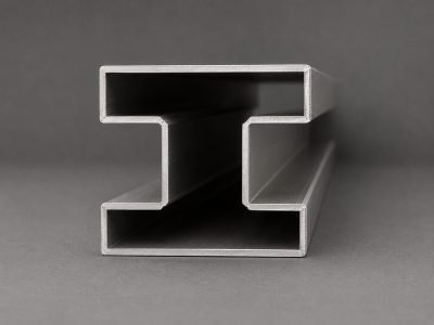
Blade Z blade 20 × 100 × 20, at 45°, V-grooved folds
Blades 18 at 83.5 mm pitch, 2,390 mm long
Supports 3 U channels 25 × 40 × 25
Sheet 1.5 mm Aluminium
Finish Mill (as supplied) What makes it different. The Z section is folded from flat sheet, so the blade length and lip sizes are free to suit the opening.
Where it is used Window and balcony screens Service yard and AC ledge screens Stair-core openings How it goes up Fix the U support channels to the wall or frame at the sides and between. Slide or set each blade into place and screw or rivet it to the channels. Work from the bottom up so each blade laps the one below. Open in the Louver Planner Add to my BOQ
2D · elevation and blade section Drawing the 3D view…
3D · one blade V top 90° V top 90° 2 mm sheet · 2 V-cuts before folding · not to scale V-groove detail · the blade: each bend line is V-cut first, then folded, so the corner closes sharp
Opening 3,000 × 3,000 mm, vertical blades
Blade C blade 25 × 150 × 25, at 0°, V-grooved folds
Blades 10 at 300 mm pitch, 2,990 mm long
Supports 3 U channels 25 × 40 × 25
Sheet 2 mm Aluminium
Finish Mill (as supplied) What makes it different. The two lips turn a flat fin into a stiff C section, so a deep fin can be made from thinner sheet.
Where it is used Façade fins and vertical sun breakers Car-park fronts Feature bands on towers How it goes up Fix horizontal support channels to the façade structure at the spacing shown. Fix each fin to the channels through its back lip. Check the fins plumb as they go up; the even pitch is what makes the façade. Open in the Louver Planner Add to my BOQ
2D · elevation and blade section Drawing the 3D view…
3D · one blade V top 90° V top 90° 1.2 mm sheet · 2 V-cuts before folding · not to scale V-groove detail · the blade: each bend line is V-cut first, then folded, so the corner closes sharp
Opening 3,000 × 2,400 mm, horizontal blades
Blade C blade 15 × 80 × 15, at 30°, V-grooved folds
Blades 20 at 122.1 mm pitch, 2,990 mm long
Supports 4 U channels 25 × 40 × 25
Sheet 1.2 mm Aluminium
Finish Mill (as supplied) What makes it different. The blade angle and pitch are set together on the drawing, so the view through can be planned before cutting.
Where it is used Rooftop plant and chiller screens Generator (DG set) enclosures Parking and service openings How it goes up Fix the support channels to the frame. Fix each blade to the channels at the set angle with brackets or screws. Keep the blade ends clear of the frame by the clearance shown. Open in the Louver Planner Add to my BOQ
2D · elevation and blade section Drawing the 3D view…
3D · one blade
Opening 2,800 × 1,200 mm, horizontal blades
Blade Flat fin 200, at 0°, laser cut
Blades 5 at 250 mm pitch, 2,790 mm long
Supports 4 U channels 25 × 40 × 25
Sheet 3 mm Aluminium
Finish Mill (as supplied) What makes it different. Flat fins need no bending; they are cut to any outline on the fibre laser and can carry a pattern of holes.
Where it is used Shading over windows and shopfronts Canopy blades Pergola tops How it goes up Fix brackets or support channels to the wall above the window. Bolt or screw each fin to the supports. Check the fins level before tightening. Open in the Louver Planner Add to my BOQ